

::: tip Prerequisites
To follow along with this tutorial, you will need to register with Speckle and install the required connectors. It takes less than 3 minutes!
For a comprehensive overview of these connectors, check our docs!
:::
Getting Started
Before getting started, check that you have a supported version of Rhino (6 or 7) and Revit (2019-22) and the Speckle 2.0 connectors installed for Grasshopper and Revit.
With everything set up, download the Rhino file for this tutorial here:
::: tip
Our Rhino and Grasshopper connectors are independent of each other, unlike in Speckle 1.0. This means you can choose whichever one best suits your workflow 😁
:::
We're also going to assume that you already have access to a Speckle 2.0 server, and you have correctly set up your account for that server in the Speckle Manager.
Sharing Revit Project Data
Let's start with the easy part: In order to create Revit elements using Speckle, we should ideally have some knowledge of the current information available in our Revit project.
Let's create a new Revit project using the default Architectural Template. You can use your preferred units. A project will be created with 2 default levels (level 0 and level 1). It should also have some default families loaded in the project.
Now, go to the Add-Ins tab, and press the Revit Connector icon. The Speckle Desktop UI should appear.
- Press the blue
+button on the lower-right corner to add a stream to the file. - Create a new stream by writing a name and clicking on the blue arrow icon. You should see the
Streamappear in the streams list.
::: tip
In our case, we'll call our stream Interop - GH/Revit - Project Data
:::
- Press the blue button at the center that reads
0 objectsand select the optionSet/Edit Objects Filter. - Go to the
Project Infofilter type, select the Project Info, Levels and Families and Types options and pressSet Filter. - Press the
Sendbutton in the Project Data stream.

That's it! We've effectively pushed our project information, including all existing levels and loaded families/types to Speckle. We'll use this information to correctly set family/type names for Revit elements.
This concludes our setup. We'll now switch to Grasshopper to receive it and use it to generate new Revit elements.
Using Revit Project Data
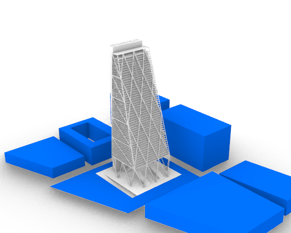
Now let's open up our fake Leadenhall building model in Rhino. You'll need to open both Rhino and Grasshopper files, as there are some Grasshopper nodes that reference geometries from the Rhino file.
Go to a blank area of your Grasshopper canvas:
- Create a
Paneland aReceivenode. - Paste the stream url we copied in the previous step into the panel.
- Connect the panel to the
Receivenode input and press the Receive button. - Create an
Expand Speckle Objectnode, and connect the received data to it.
Once done, it should look like this:
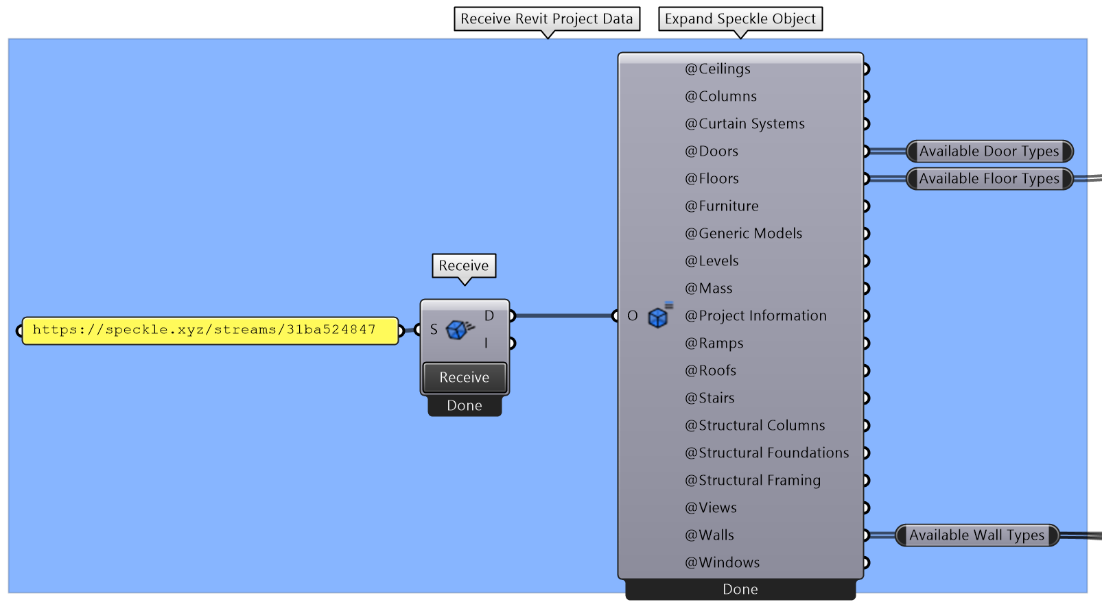
Most of the outputs will also be Base objects, meaning you'll have to expand them to inspect their properties (more on this later when using family types).
Sending Geometry to Revit
We'll start by sending some contextual geometry to Revit, along with the surrounding street lines and plot terrain. For this, we'll first create a Speckle Object to organize our data.
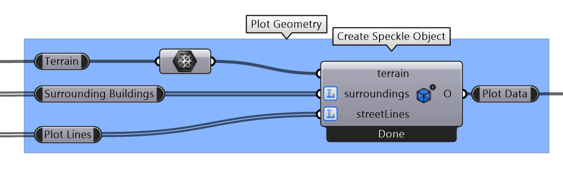
::: tip
Remember you must correctly specify the Access Type for each input to generate the right amount of Base objects.
Inputs set with List Access will be shown with an L icon beside them.
:::
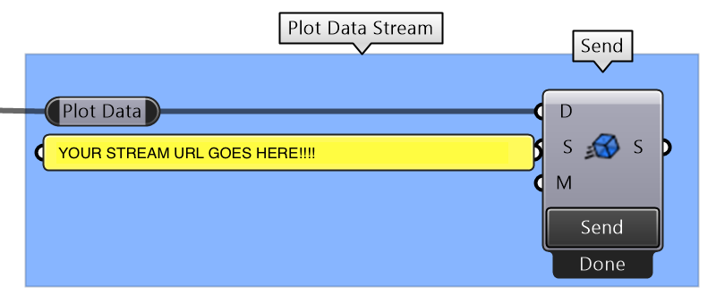
We'll also need to create a new stream in our server to send our data to. Create it, name it Interop - GH/Revit - Plot Data, and copy its url.
Then, we can just plug in the geometries directly into their respective inputs. Connect it to a Send Data node pointing to the stream we just created and press Send.
In Revit, add the stream to your DesktopUI and press Receive. Here's a quick peek of the process:
::: tip About sending BREPs
Rhino BREP support still has some limitations we are working on improving, but others are strictly imposed by the Revit API. In order to ensure unsupported geometric objects still get represented when importing to Revit, we provide a fallback value for every BREP in the form of a Mesh.
In short, this means whenever a BREP conversion fails in Revit, the resulting object will still be generated in the model, only as a tesselated representation of the smooth BREP. It's nice to have a Plan B.
:::
Controlling the DirectShape Conversion
As you may have noticed, our surrounding buildings have been created in Revit as Generic Models. This is the default conversion behaviour when sending geometry elements that are not directly supported by Revit (such as meshes or breps).
In order to control this behaviour, we can use the Schema Builder node.
::: tip SchemaBuilder Node Pop-up
When first placing the node, a pop-up window will appear allowing you to select the object type you want to create. These are organized into two main categories:
- Built Elements: These are Speckle elements created to support common built elements (beam, wall, slab, level...) accross the entire Speckle ecosystem.
- Revit Elements: These are specifically designed to support Revit specific entities and workflows.
:::
- Drag a
Create Schema Objectnode to your canvas. - From the pop-up, select
DirectShapeand press ok. A new node and a dropdown should appear. - Select
Massfrom the dropdown list. - Connect the surrounding building geometries to the
baseGeometriesinput. Graft the input to generate one direct shape per geometry. - You'll also need to connect a panel with a desired name for each
DirectShape.
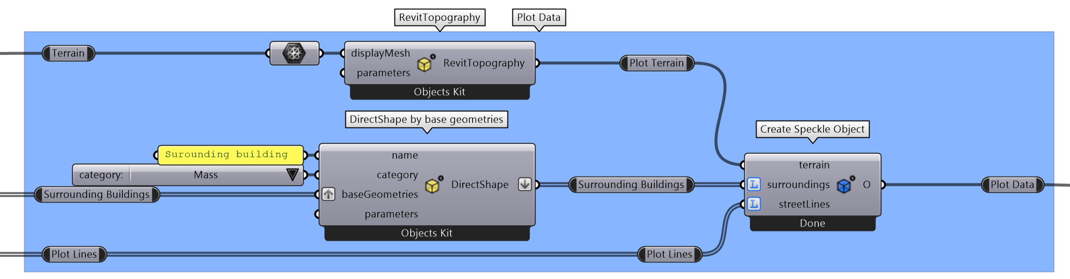
Let's also send the terrain as a native RevitTopography object.
- Drag a
Create Schema Objectnode to your canvas and select theRevitTopographytype. - Connect the terrain mesh to the revit topography
displayMeshinput.
It should end up looking like this:
Now swap those direct shapes for the original geometries and send them.
In Revit, once you get the notification that data was changed, press the receive button. You should now see the surrounding buildings appear as Massing objects.
::: tip
If you don't see the surrounding buildings, ensure your Visibility/Graphics (or View Template) settings are set to display elements of the Massing / Site category.
:::
Generating Floors and Levels
Now that we have our plot and surrounding buildings set-up, let's proceed with the creation of the levels and floor slabs for each level.
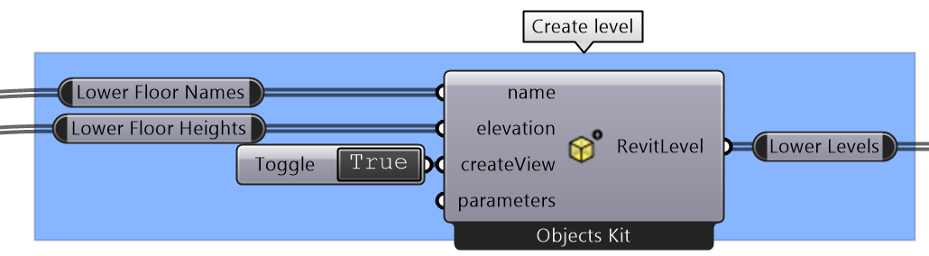
Creating Levels
- Drag a
Create Schema Objectnode to your canvas and select theRevitLeveltype. - A Revit level requires a name and elevation. You'll also need to specify whether to create a view to go along with the new level.
- Connect the
lower floor namesandlower floor heightsto their respective inputs in theRevitLevelnode.
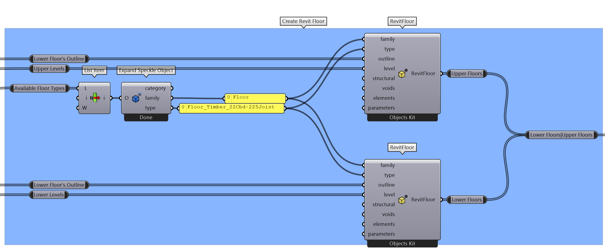
Creating Floors
Now we'll create some native Revit floors, using the levels we previously created and the curves available on the Upper/Lower Floor Outlines nodes. We'll also need to select a floor type from one of the available floor types we received from Revit.
::: tip
To select a specific floor type, first select an individual type with a list item node, and then use the Expand Speckle Object node to inspect its properties.
:::
- Create two
SchemaBuildernodes withRevitFloortype. - Connect the selected family name and type.
- Connect the respective levels and outlines (upper/lower) to each
RevitFloornode.
Creating Beams
In this case, we do not have much information about the structural beams since they are modelled as simple lines. This is the perfect scenario in which to use Speckle's BuiltElements.
These are simple representations of common BIM elements, that require a minimum amount of input. These elements will be appropriately converted to native elements on each target platform wherever possible.
In the case of a BuiltElements.Beam, the input required is only the axis line of that beam.
- Drag a
Create Schema Objectnode to your canvas and select theBeamtype (notRevitBeam). - Connect all truss lines to the
baseLineinput. Since we don't really care about the data structure they're organized by, we can flatten the input.
Creating the Walls
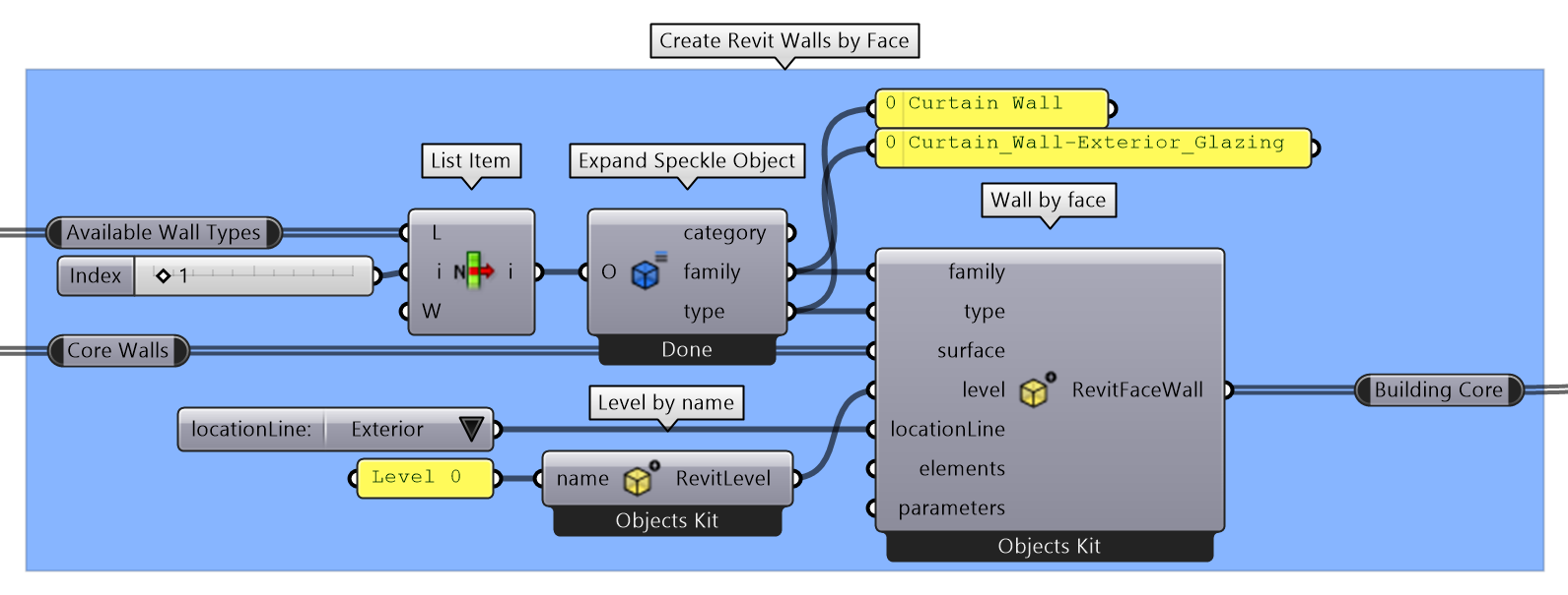
Core walls
Just like with floors, we can create walls using the Create Schema Object node. There are several ways to create a wall, but for the Core Walls, we're going to create them with the Wall by Face type. This takes a surface as a reference to create a wall in revit with the same shape.
- Drag a
Create Schema Objectnode to your canvas and select theWall by Facetype. - Locate the node called
Core Wallsand connect it to thesurfaceinput. - Select a category from the available wall types we received from Revit and connect its family name and type.
- The last thing we need is a level, but in this case, we already know there is a level called
Level 0on our project, which is at ground level. We can reference it using theLevel by nameschema. - Drag a
Create Schema Objectnode to your canvas and select theLevel by name. - Connect a panel with the text "Level 0" to its only input, and connect the resulting level into the
Wall by Facenode.
Interior Walls
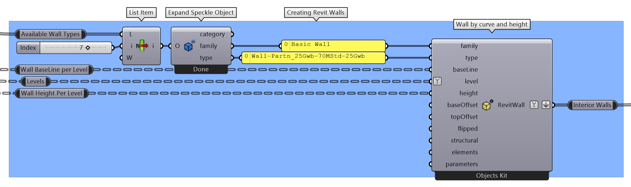
We have a bunch of interior walls we haven't done anything with yet. Let's create them using a line and a height.
Drag a Create Schema Object node to your canvas and select the Wall by curve and height type.
Connect the nodes Wall Baseline per leveland Wall Height per level to the baseLine and height input respectively.
Connect the filtered levels node to the level input.
::: tip
Notice that, since not all levels have walls, the levels have been filtered to contain only the ones that are to be used.
:::
You can flatten the output of the node, as we won't be needing that data tree structure anymore.
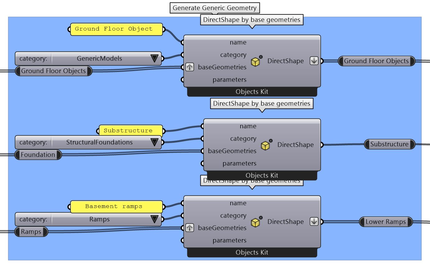
Categorizing Generic Geometric Objects
For anything that cannot be directly translated into Revit elements, you can still send them directly, as we saw in the first step. Just as we did with the surrounding buildings, we can categorize the Ground Floor Objects, Foundation and Ramps as DirectShape objects with their appropriate categories.
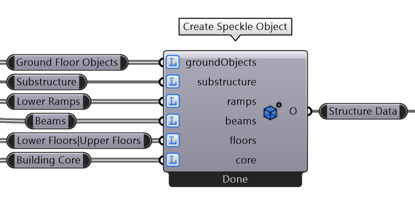
Organize the Building Structure
Until this moment, we've been creating several Revit elements we want to send. Before doing so, let's organize that data into a single Speckle Object to keep everything tidy.
We have several parts to send:
- Floors
- Core walls
- Interior walls
- Beams
- Objects at ground floor
- Substructure
- Ramps
- Drag a new
Create Speckle Objectnode. - Create inputs for each of the object types we just created.
- Connect everything appropriately.
::: tip
Always remember to set the access type of your inputs appropriately.
:::
Sending the Building Structure
In the Speckle Web App, create a new stream to send the structure data to. Copy its url. In Grasshopper, create a Send node and a panel with the url of the stream we created earlier to share the structure.
In Revit, add the newly created stream to the DesktopUI and press Receive. You can see the entire process in the animation bellow.
Create Adaptive Components
Adaptative Component families in Revit are a ton of fun. They are defined by a set of points, flexing to adapt their geometry as these adaptive points move around.
::: warning
In order to correctly create Adaptive Component family instances, the specified family must be loaded into the Revit project.
The amount of points provided must also coincide with the amount of points the Adaptive Component family uses internally.
:::
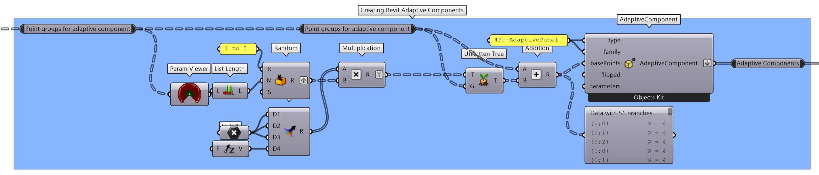
You'll find a very simple adaptive component called 4Pt-AdaptivePanel along with the rest of the files of this guide.
In the file, we already created some curved square panels to act as a fancy roof shading. In the grasshopper file, you'll find a node called Point groups for adaptive component, containing the 4 corners of this panels individually grouped.
Sending Adaptive Components to Revit using Speckle is quite easy:
- Drag a
Create Schema Objectnode to your canvas and select theAdaptiveComponenttype. - Input the appropriate
familyandtype(in our case, they are both the same:4Pt-AdaptivePanel) - Connect the grouped points to the
basePointsinput. The component would generate anAdaptiveComponentobject for every group of points. - Create a new stream on the server to hold this adaptive panels and create a
Sendnode pointing to that stream. - Send the
AdaptiveComponentsyou just created.
In Revit, add the stream you just created using the Desktop UI and receive the data. Your panels should appear on the top floor of the building.
Using Branches to Swap Design Alternatives
This is a perfect moment to introduce the concept of branches and how you can leverage this feature to alternate between different design options.
- Go to the stream's url in your web browser, and create a new branch called
design-option-2. - Copy the url of the
branchpage (it should end in/branches/BRANCH_NAME) - On the grasshopper file, modify the points in any way, like modifying the
seedinput in theRandom numbersnode. - Change the
stream urlfor thebranch urlwe just copied and press send.
In Revit, you'll notice there's an update notification in the Roof Panels stream that specifies there have been changes in a different branch. You need to switch branches to receive the new data.
- Click the branch name on the stream.
- Select the branch we just created.
- Click the
Receivebutton.
You should see the new panels update to reflect the new design option. To go back to the previous version, you can always go back to the main branch.
Using Speckle in the Family Editor
::: warning
🚧 This section is still under construction 🚧
:::
Populating Family Instances in the Model
::: warning
🚧 This section is still under construction 🚧
:::
Known Issues
Speckle 2.0 is currently in beta mode. You can find any known issues on our GitHub Repo Issues page.
Conclusion
We hope you enjoyed this tutorial and found it useful!
Speckle is an Open Source project and we really ❤️ feedback, so if you have any questions, comments, critiques, or praises please let us know on our community forum.